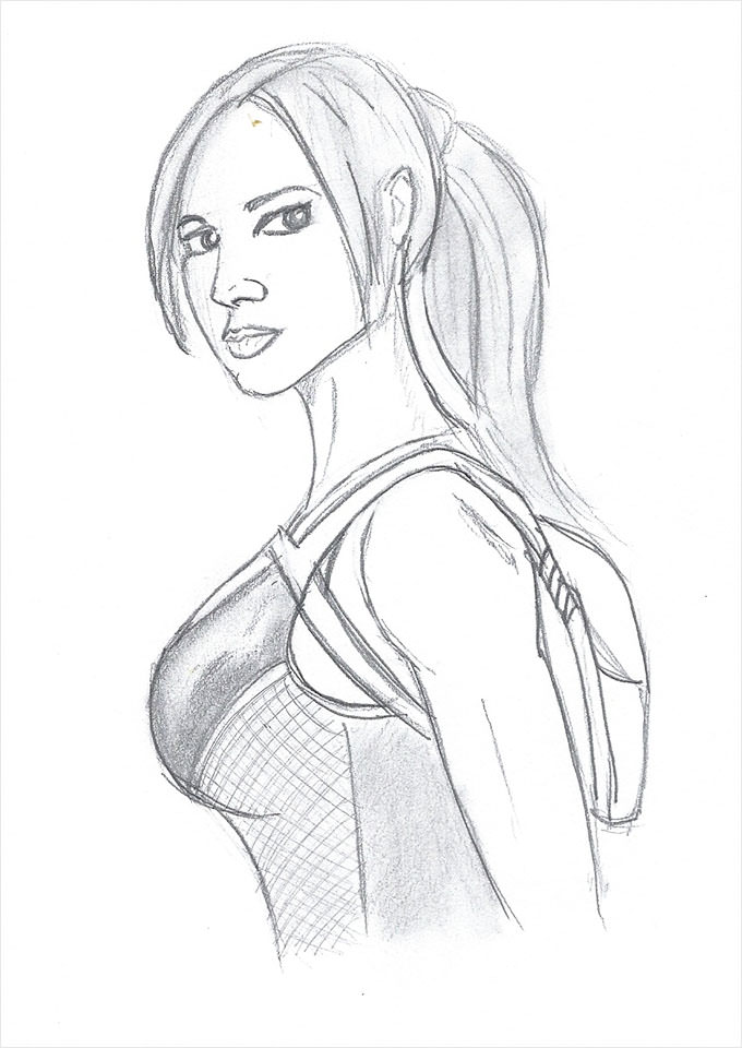
27+ figure drawing construction
Jan 11 2022 - Explore Farahs board Figure Construction on Pinterest. Highway Traffic Standards Manual June 2015 Amended November 2016.

Pin By Mk Sicree On Stuff About Everything Drawing Face Shapes Drawing Tutorial Face Drawing
A demo in a students drawing pad at ArtCenter today.

. Cages or wells except on chimney ladders shall be built as shown on the applicable drawings covered in detail in figures D-7 D-8 and D-9 or of equivalent construction. Technical Report Documentation Page 1. The figure shows the layout of a typical sheet showing the drawing frame a typical title block parts list bill of.
Larger sizes are necessary for bigger properties. But regardless of the blueprint paper size the plan will have the following. When Condition C exists available.
46-2003 11031 - 11035 6 Hrs 7 Construction of scales and diagonal scale 11136 6 Hrs Total 72 Hrs Instructions to the Instructors. 3 Free hand drawing 1719 - 1723 6 Hrs 4 Drawing sheet sizes title block and item list 1824 6 Hrs 5 Method of presentation of engineering drawing 1925 - 1930 12 Hrs 6 Symbolic representation as per BIS SP. 191027d1ii Cages or wells except as provided in subparagraph 5 of this paragraph conforming to the dimensions shown in figures D-7 D-8 and D-9 shall be.
Ad One Stop Solution For All Your Architectural Engineering and Construction Needs. Up to 4 cash back The drawing sizes for construction plans will come in several different formats with 18 x 24 and 24 x 36 being the most common. Relative Proportion of the Human Parts HeadBodyneck is four heads Arm is three heads Hand is two third of head Leg is Four heads Feet is one head.
Figure 1 Typical Site Plan. Manatee County Public Works Standards Part 3. Ideal Human Proportion Normal Human Proportion.
I Abstract This project examined the design of a landbased wind turbine considering various alternatives including soil and foundation type turbine size and type tower design type of site and wind speeds. Figure construction and proportional systems. Figure Drawing Proportion and Construction By Goh Ee Choo.
See more ideas about drawing tutorial drawings cartoon drawings. 7018 Likes 9 Comments - Will Weston willwestonstudio on Instagram. Figure 7-16 warning alarm.
Section 61 DRAFTING MANUAL Page 2 Dimensioning and Tolerancing August 1993 Symbols Update 47 24 Depth - A downward-pointing arrow is used for the depth symbol and it is placed in front of the depth value in such applications as for counterbore and hole depths. Map of JPL and Surrounding Area4 Figure 2-2. IEEE Std 315-1975 Reaffirmed.
Carbon Tetrachloride Concentrations in MP-32. Drawings to be in one electronic file utilizing the Layout Tabs feature in AutoCAD 2009. Basic A frame gantry hoist LK Goodwin 2012 This design is relatively easy to assemble while it is lying down but would most likely require two people to stand up.
Unit 571 New Smyrna Beach FL 32128 386-882-EZCE3923. The station plane is. Engineering Working Drawings Basics Page 2 of 22 Drawing Sheet Layout Standard layouts of drawing sheets are specified by the various standards organizations.
111 Pictorial Drawing Perspective Drawing Definitions Refer to Figure 12-40 Sight lines which lead from the points on the card and converge at the eye are called visual rays. Engineering Fluid Diagrams and Prints iv REFERENCES ASME Y145-2009 Dimensioning and Tolerancing. Carbon Tetrachloride Concentrations in MP-33.
But you can also find larger plans at 30 x 42 and 36 x 48. Ad When you choose WMD Squared your drafting packages can scale with you and your products. We Can Help You With Everything From Design Engineering to General Contractor Selection.
We understand the complexities of manufacturing and work to streamline your process. Guidelines for the Design of Buried Steel Pipe July 2001 i Acknowledgments The following people with their affiliations contributed to this report. The picture plane is the plane on which the card is drawn.
All drawings shall be delivered to the Coast Guard in AutoCAD 2009 compatible dwg file format and in accordance with Naval Engineering Manual M90006 series to allow for the life-cycle drawing maintenance. Report Date October 2006. Figure Drawing proportion and construction.
Engineering phase of the project and included in the construction drawings through standard details are acceptable. Figure 7-17 drawing for the potentiometer. Figure 711 General location and layout of boreholes for sequential 727 blasting Figure 712 Results of over-blasting in an auxiliary spillway 728 Figure 713 A materials placement data table and corresponding 732 cross section for a zoned embankment Figure 714 Proctor curve 733 Figure 715 Crumb test ratings 738.
Plan View of VOC Soil Vapor Plume May-June 1998.

Imgur Com Design Reference Drawings Drawing People

27 Cartoon Drawings Free Jpg Format Download Free Premium Templates

56 Ideas Drawing Poses Female Superhero For 2019 Drawing Reference Figure Drawing Reference Drawing Poses

How To Draw Naruto Uzumaki Step By Step Drawing Tutorial How To Draw Step By Step Drawing Tutorials Naruto Drawings Step By Step Drawing Drawing Tutorial

Pin By Noir Angel On Cizim Body Pose Drawing Art Reference Poses Art Reference

Pin On Draw

27 Cartoon Drawings Free Jpg Format Download Free Premium Templates

27 Cartoon Drawings Free Jpg Format Download Free Premium Templates

Anatomy Art Drapery Drawing Anatomy Sketches

27 Ideas Drawing Poses Back Anatomy Reference For 2019 Anime Drawings Tutorials Drawing Body Poses Drawing Poses

Symetry On Abs Anatomy Sketches Anatomy Drawing Human Anatomy Art

27 Cartoon Drawings Free Jpg Format Download Free Premium Templates

Drawing Basics Construction Drawings Basic Sketching Basic Shapes

Body Art Back Painting Figure Drawing 27 Ideas Painting Drawing Bodyart Art 763852786783562430 Art Drawings Sketches Drawing Sketches Art Sketchbook

63 Super Ideas Drawing Tutorial Body Male Artists Figure Drawing Reference Anatomy Art Sketches